Woah! We’re falling, but how do we stop it? That’s right: with a parachute!
Parachutes come in all shapes and sizes, with each shape having a unique set of advantages and disadvantages. We’ve got to figure out how to choose the right one, and then figure out how to make it. Here’s how we did it:
The Requirements
Let’s first take a look at what exactly the parachute has to do:
- The parachute connection must be able to withstand up to 50N of force
- The parachute must be able to decelerate the satellite to a descent rate of 5-12m/s (8-11m/s preferred)
So how are we going to achieve that? To be able to withstand the force required, we’ll reinforce the connections between the strings and the parachute, as well as between the strings and the satellite. To be able to decelerate our satellite to the specified descent rate, we’ll need to do calculations and make some key decisions:
What Math Do We Have to Do?
Let’s take a look at how we’ll calculate what parachute we’ll need. As per the European Space Agency, the formula for this is the following: \(A=\frac{2mg}{C_D \rho v^2}\) Where \(A\) = canopy surface area, \(m\) = mass of the satellite, \(g\) = acceleration due to gravity, \(C_D\) = drag coefficient of the parachute, \(\rho\) = local density of the air, \(v\) = descent velocity in m/s.
We know that the mass of the satellite is approximately 325g and the acceleration due to gravity is approximately \(9.81m/s^2\). The local density of the air is assumed to be constant at \(1.225kg/m^3\), and we’ll aim for a descent velocity of 8m/s to provide us some buffer room. If it’s too slow, we can always cut the parachute down. It’s a lot harder to make it bigger. As for the coefficient of drag, that’ll depend on what shape of parachute we choose. Let’s look into that.
Decisions, Decisions…
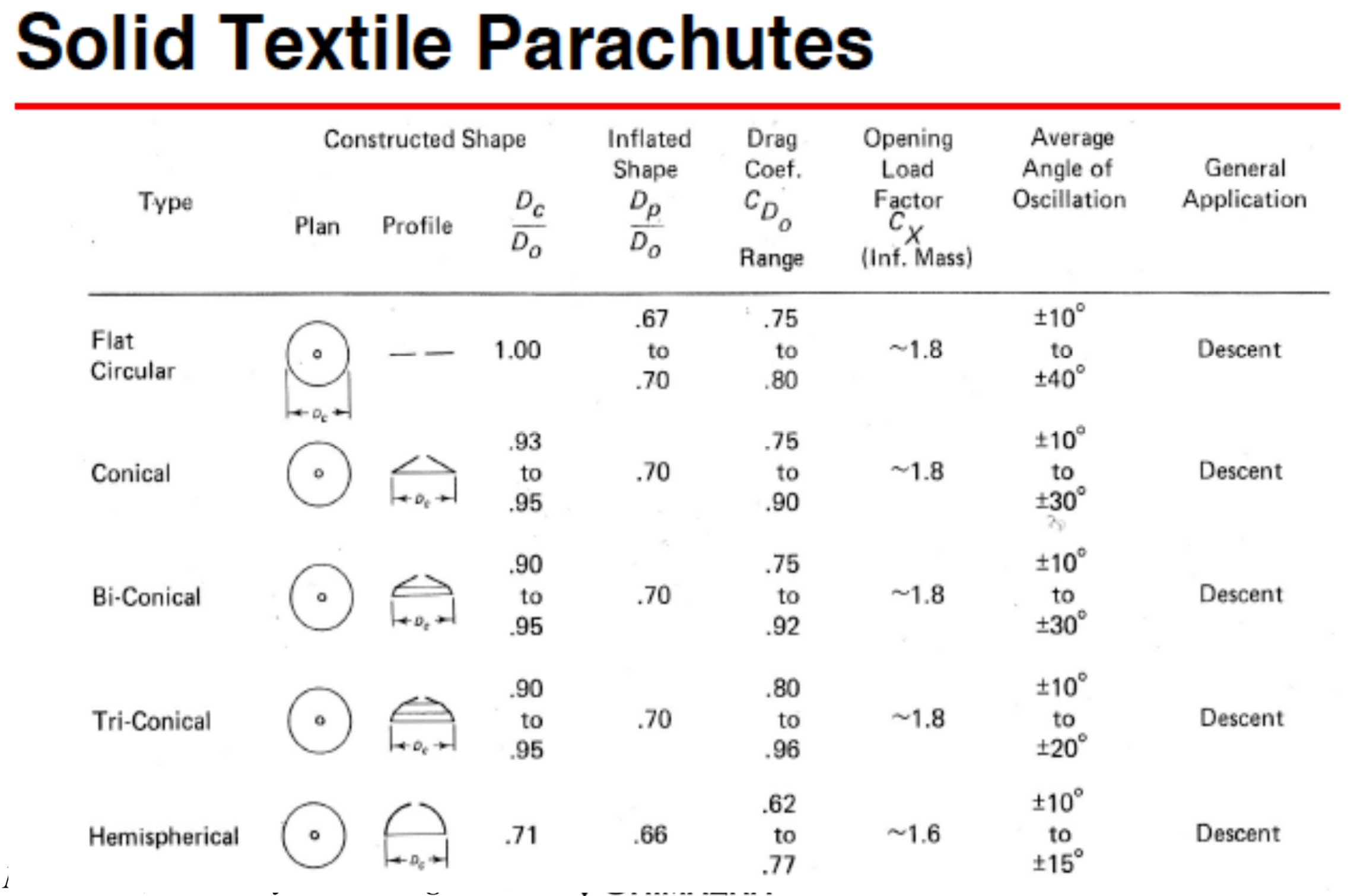
 To figure out the different drag coefficients, we took a look at a slideshow from Utah State University. It lists out the respective range of drag coefficients on slides 14-15. As well, it lists the average angle of oscillation of each shape, which is how much the parachute will rock from side to side.
We want to find a design that maximizes the drag coefficient so we can minimize the amount of parachute material needed, minimizes the average angle of oscillation to make the images taken by the camera as stable as possible, and is easy to design and manufacture.
While the slotted parachute designs provide the most stable designs, they fail they first and third requirements. They are difficult to manufacture and design, as well as wasting significant amounts of material relative to the small drag coefficients they provide.
That leaves us with the solid textile parachutes: We can eliminate the flat and conical parachutes due to their incredibly high angle of oscillation. That leaves us with the hemispherical parachute, which offers a fair balance of all aspects. This has a coefficient of 0.62-0.77.
Now, let’s figure out how big our hemispherical parachute has to be:
Number Crunchin!
Now that we have all the information we need, we can calculate required surface area:
\(A=\frac{2mg}{C_D \rho v^2}\)
\(A=\frac{2(0.325)(9.81)}{0.62(1.225)(8^2)}\)
\(A=0.131182m^2\)
\(A=1311.82cm^2\)
We know that the surface area we calculated is actually the projected area: the area of the circle that makes up the bottom of the hemisphere. Well, now that we have the required surface area, let’s find how big we need the parachute sections to be. To do that, we’ll need to first find the radius of the bottom of the hemisphere:
\(\pi r^2=1311.82\)
\(r=20.43cm\)
Having found the radius of the circle, we need to find the height of each parachute panel. We can do this by finding a quarter of the perimeter of a circle with the same radius:
\(H=\frac{2 \pi (20.43)}{4}\)
\(H=32.09cm\)
Now we know that each panel has to have a height of 32.09cm.
Designing the Parachute
When designing the panels for a parachute, you have to make the curves using complex equations so that when everything is sewn together, it fits together into a perfect hemisphere. As well, there is a specific ratio of height and width for every panel, depending on how many there are.
To overcome these requirements, we decided to trace a screen capture of an 8 gore panel diagram using Bezier curves in Inkscape. This allowed us to produce a vector image with all the correct dimensions and curves that we could scale as required. We then scaled the parachute to the necessary size.
We also included a hole in the apex. This hole releases the excess pressure that might otherwise buildup under the canopy and cause it to oscillate, which is something we’re aiming to avoid.
As well, there’s holes in the bottom of each panel. These will be the points where we can secure the strings that hold the parachute on to the satellite.
Cutting to the Chase
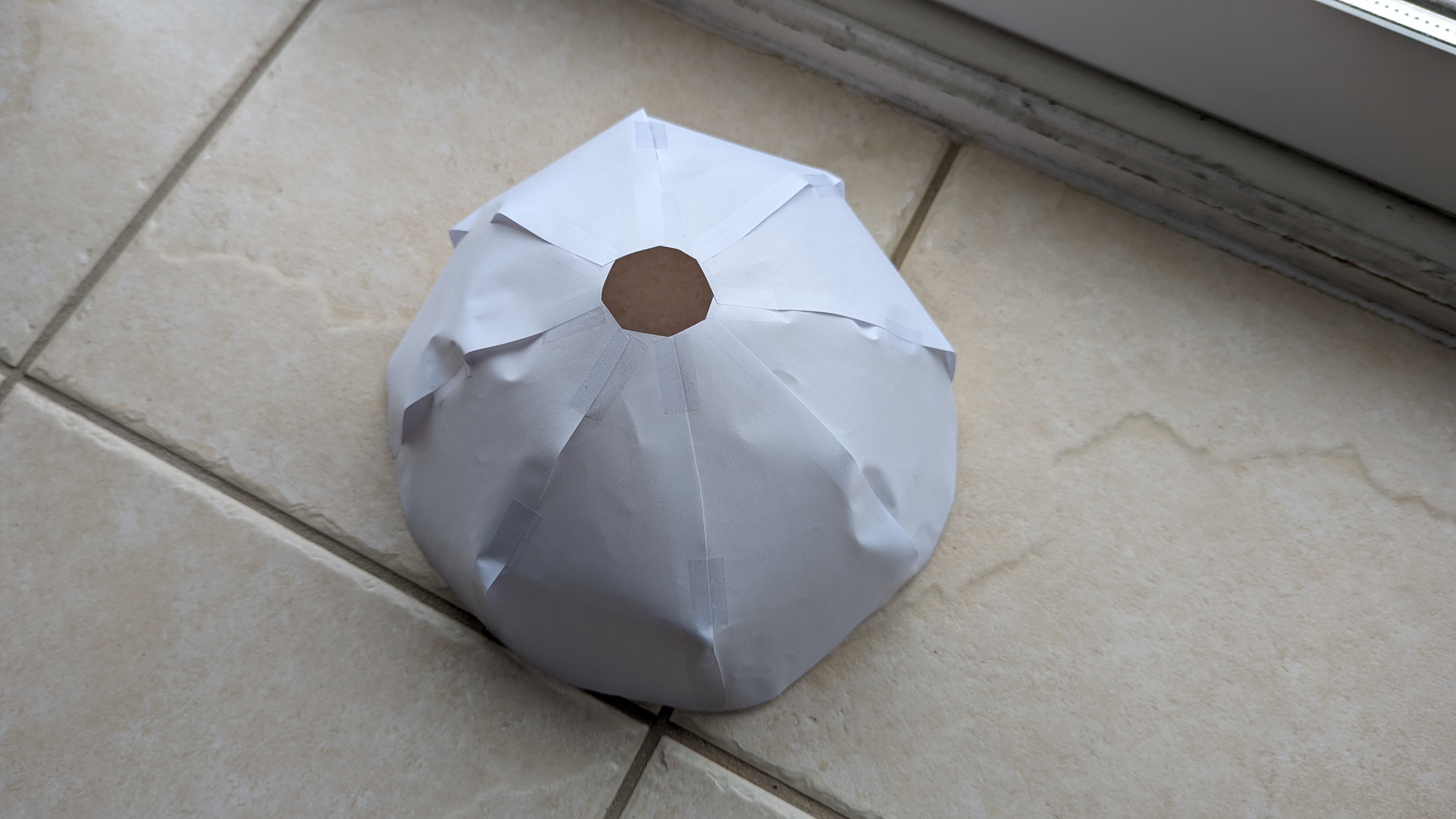
 We first started by validating that, indeed, the parachute design would work. We printed out the panels at 90% scale so they could fit on a standard A4 paper. We then cut them out and taped them together to test the fit. Thankfully, everything fit together, so it was fine to move onwards.

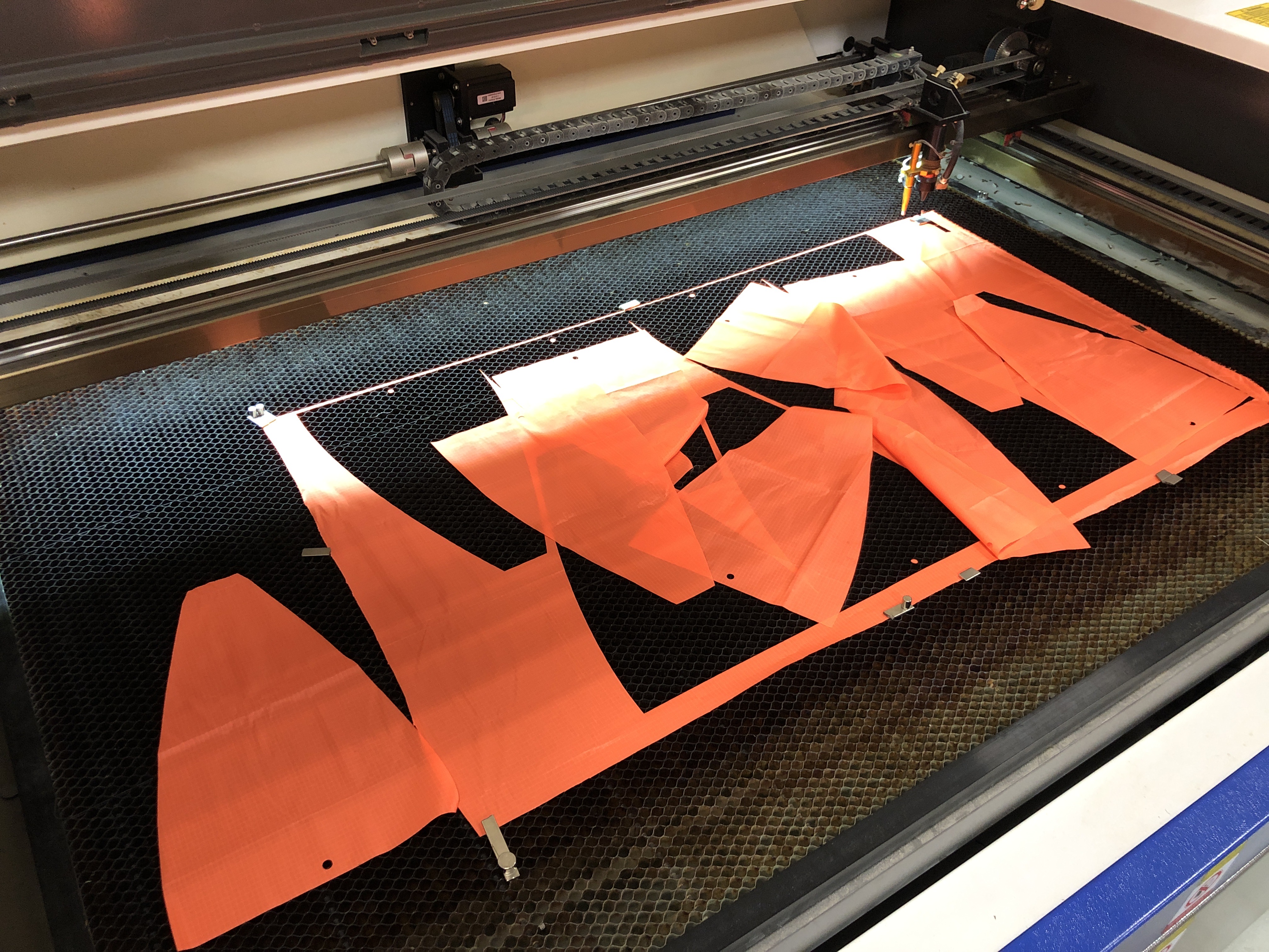
 Once the parachute has been cut, we can then sew the panels together. After having been sewn together, the parachute adopts its intended hemispherical shape.
Now that the parachute has been assembled, let’s attach it to the satellite itself.